
Why LowDrift FSR?
Emerging "smart shelf" technologies simplify inventory management, help detect theft, and improve customer experience. Force Sensing Resistors (FSRs) are often considered for use in these applications because of their low cost, high dynamic range, and ability to precisely identify product footprints, but drift can pose a significant challenge.
All Force Sensing Resistors drift, or become more conductive over time, under a fixed load. This effect can be very significant. The conductance of some FSRs will increase by more than 30% in 48 hours. Such high rates of drift complicate the use of FSRs in scale-type applications, requiring sophisticated sensor models and heuristics. Sensitronics' patented LowDrift FSR technology aims to make FSRs more applicable to these types of applications by reducing drift to levels that are easily managed, or in some cases ignored.
The charts below provide a snapshot of our LowDrift FSR technology. The first relates the logarithmic drift rate to pressure for the LowDrift FSR ink as well as our mature FSR inks, collectively identified as Standard FSR:
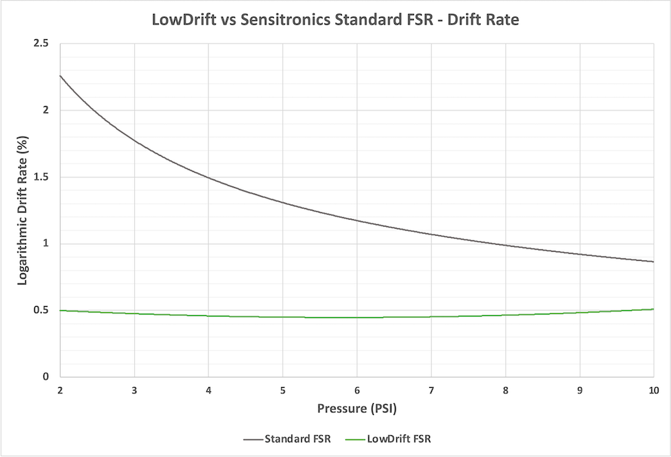
For a given period of time, the total drift can be estimated using the following formula, where driftlog is the logarithmic drift rate and t is the duration in seconds:
drifttotal = driftlog * log10(t)
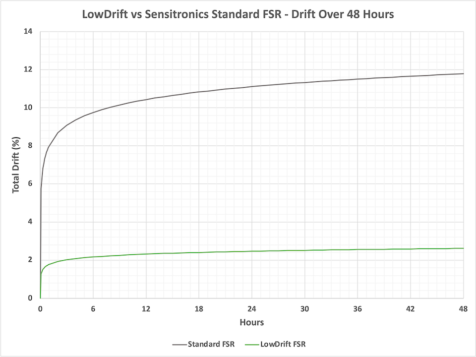
The next chart plots the total drift over 48 hours for both LowDrift and Standard FSR. The pressure is fixed at 2 PSI. It can be seen that under this constant pressure, the Standard FSR inks drift almost 12%. The LowDrift FSR ink drifts only about 2.5%, or 80% less than the Standard FSR:
Note that these drift percentages describe a change in the conductance, not the resistance, of the sensor. FSR characteristics are commonly described in terms of resistance, however the resistance of an FSR has a logarithmic relationship with the applied force. This logarithmic relationship is one of several reasons why circuits incorporating FSRs, and especially those used for collecting data from FSR matrixes, employ transimpedance amplifiers to instead measure the current passing through the FSR, and hence the FSR's conductance. Consequently drift is also observed as a change in conductance. The conductance of an FSR generally has a much more linear relationship with applied force.
FSRs come in a variety of types, chiefly ShuntMode and ThruMode. ShuntMode parts are generally the most cost-effective and the easiest to integrate, owing to construction that requires only a single circuit layer. The graphs above were generated using data gathered from these types of FSRs. ThruMode, which has two opposing circuit layers, tends to require higher quantities of conductive ink but is particularly well suited to high-density matrixes (sensors can be as small as the intersection of two circuit traces). In our testing, ThruMode parts benefited less from LowDrift FSR ink, showing improvements of approximately 50% (total drift over time) versus up to 90% for their ShuntMode counterparts. Given these factors, we would suggest evaluating ShuntMode FSRs first unless your project requires especially high sensor densities.
We welcome the opportunity to answer any questions you might have. This is a significant and ongoing R&D effort within Sensitronics, and we'll provide additional updates as the work continues.
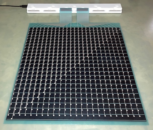
Pictured above: Evaluation kits will soon be available for LowDrift FSR. These will include a 18x18in flexible FSR matrix with approximately 576 sensing points, data collection electronics, and software for Microsoft Windows. For pricing and availability, email info@sensitronics.com.