
Part 3: Hardware Connections
Alright, time for breadboarding / the good part.
In the previous section, we discussed two resistance values that we need to read to determine position + force. Analog-wise, we need to use two different circuit, but we'll switch back and forth by simply changing pinModes on the Arduino.
Here are the equivalent circuits:
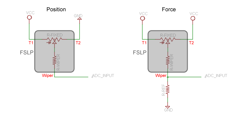
In Position mode, ratiometric position is equal to VADC_INPUT / Vcc.
In this tutorial we'll just take a relative / ballpark force reading, and consider the effect of RFIXED-1 in parallel with RFIXED-2 to be negligible. If we needed better accuracy, we'd use the known value of RFIXED and our position readings to calculate the two parallel segment resistances, and null the added resistance in software.
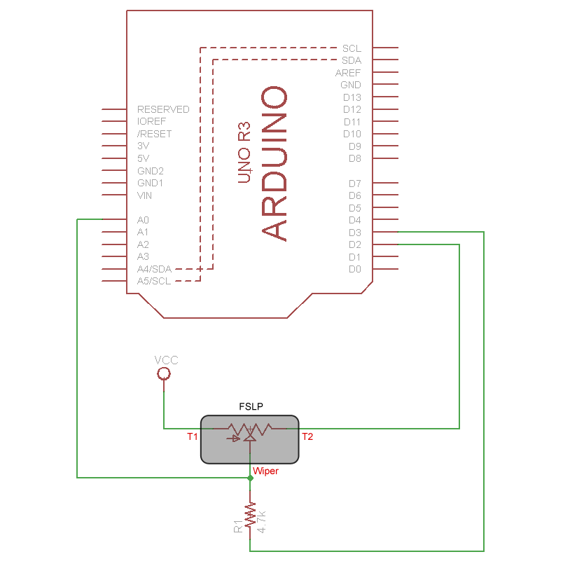
The Actual Circuit
And here's the actual circuit we'll breadboard, it's pretty straightforward.
Important Note: Your sensor may have different connectors, or no connectors (in which case you'll need an FPC connector or punch-crimper). DO NOT attempt to solder directly to the sensor membrane. It will melt.
FSLPs tend to work best on a flat surface. You might want to tape the sensor down by the edges so it doesn't slide around.
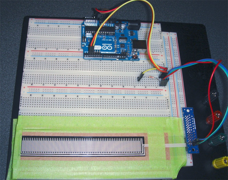
Here's what ours looks like on the breadboard (click image for full size).
Our sensor is plugged into an FFC connector on the underside of a small adapter board, and we used some cardboard and tape hold things in place.
Could be prettier, but it'll work!
Next up, an example Arduino sketch...